

Simple force producing device
- The motoring and generating action is basically a reversible process i.e. the same machine is capable of operating either as a generator or as a motor depending upon whether the supplied power is mechanical or electrical.This is illustrated in Fig.3.2. However, in practice, devices may be designed and constructed to suit one particular mode of conversion or the other.And machine tools it is called a motor [Fig.3.1 (b) ]. In other words, it can be stated that the generator converts mechanical power ωT into electrical power EI and motor converts electrical power EI into mechanical power ωT.
 |
| electrical and mechanical system |
An electromechanical energy conversion device is a link between an electrical and mechanical system and electro-mechanical energy conversion needs the presence of natural
phenomena which interrelate electric and magnetic fields on one hand and mechanical force and motion on the other.
The most important phenomena which make this conversion possible are :
- Whenever a current carrying conductor is placed in a magnetic field in such a way that a component of the length of the conductor is perpendicular to the field, a force will exist between the conductor and the field.
- Whenever a piece of ferromagnetic material is placed in a magnetic field, a force is experienced upon the material tending to bring it into the position of the densest portion of the field.The force tends to align the material specimen so that the reluctance of the magnetic path passing through the material will be at a minimum.
- A force of attraction is exerted upon the charged plates of a capacitor.
- Whenever a piece of dielectric material is located in an electrostatic field, a force is experienced upon the material tending to bring it into the densest portion of the field. In case the specimen of material is of unsymmetrical configuration the force tends to align its long axis with the electrostatic field.
All of these phenomena involve a force relation that exists between either a magnetic field or an electrostatic field and a material structure (matter). Thus, if relative motion between the field and the material structure is associated with this force, energy conversion must occur between the field and the mechanical system associated with the structure. All of these phenomena, therefore, provide a means for electromechanical energy conversion i.e. interchange of energy between a magnetic field ( or an electrostatic field), and a mechanical system. The medium for the energy transfer is either a magnetic field or an electrostatic field. If the motion is in a direction opposite to that of the force resulting from the electromagnetic or electrostatic relations the motion is developed by the mechanical system, and mechanical energy is converted into energy associated with the electrical system. On the other hand, if the motion is in the direction of the force resulting from the electromagnetic relation, the motion is caused by the associated electrical system, and electrical energy is converted into mechanical energy.
For instance in phenomenon 1, when the motion is in the direction of the electromagnetic force, electrical energy from the electric source which causes the current to flow in the conductor is transferred through the associated magnetic field into mechanical energy. While in case the motion is opposite to the direction of the electromagnetic force, mechanical energy is transferred through the associated magnetic field into electrical energy of the system connected to the current carrying conductor.
In this text, we are primarily interested in electromechanical energy conversion by means of continually rotating machines. The energy conversion in most of these machines with their present-day construction is produced through the presence of both phenomenon 1 and phenomenon 2. In both of these phenomena, the magnetic field is the medium for the energy transfer. Also, in all of our present-day continually rotating electrical machines, the energy of the magnetic field is directly associated with the energy of an electrical system external to the machine. Thus, the energy transfer involved always is between a mechanical system and an electrical system through the medium of a magnetic field.
For understanding the behavior of rotating machinery, a simple physical picture is quite useful. Associated with the rotor structure is a magnetic field, and similarly with the stator; one can picture them as a set of north and south poles associated with each structure. Just as a compass needle tries to align with the earth's magnetic field, these two sets of fields attempt to align, and torque is associated with their displacement from alignment. Thus in a motor, the stator magnetic field rotates ahead of that of the rotor, pulling on it and performing work. The opposite is true for a generator, where the rotor does the work on the stator.
 |
| simple force producing device |
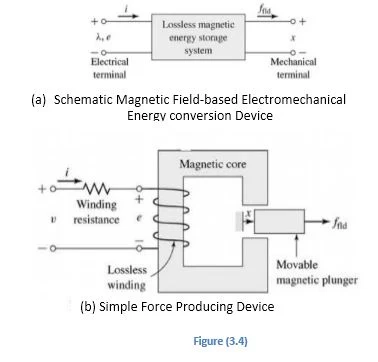
Various techniques have been evolved for calculation of the net forces of concern in electromechanical energy conversion. The technique usually employed is known as the energy method and is based upon the principle of conservation of energy. The basis for this method can be understood with reference to Fig. 3.4 (a) where a magnetic field-based electromechanical energy conversion device is indicated schematically as a lossless magnetic energy storage system with two terminals. The electric terminal has the terminal variables voltage e and current I and the mechanical terminal has the terminal variables force f(field) and position x. This sort of representation is valid in situations where the loss mechanism can be separated out from the energy-storage mechanism; in these cases, the electrical losses such as ohmic losses can be included as external elements connected to the electrical terminals and the mechanical losses such as frictional
losses can be induced externally to the mechanical systems. Fig.2.4 (b) shows a typical example of such a system; a simple force-producing device with a single coil forms the electrical terminal, and a movable plunger serves as the mechanical terminal.
The interaction between the electric and mechanical terminals, i.e. the electromechanical energy conversion, occurs through the medium of the magnetic stored energy.Since the energy-storage system is lossless, it is a simple matter to write that the time rate of change of W(field) , the stored energy in the magnetic field, is equal to the electric power input less the mechanical power output of the energy-stored system i.e.
d W(field) dt=ei-ffielddxdt=idψdt-f(field)dx dt
∵e=Ndϕdt=dΨdt
Or dW(field) =i dψ-f(field)dx
Equation (3.6) permits us to solve the force simply as a function of the flux linkage ѱ and the mechanical terminal position x. This result comes about as a consequence of our ability to separate the losses out of the physical problem, resulting in a lossless energy storage element, as in Fig.3.4 (a).
 |
| single core rotor |
Equation (3.5) and (3.6) form the basis for the energy method. This technique is quite powerful in its ability to compare forces and torques in complex situations of electromechanical energy-conversion systems. It is to be noted here that this power comes at the expense of a detailed picture of the force-producing mechanism. The forces themselves are produced by such well known physical phenomena as the Lorentz force on the current-carrying element, or the interaction of the magnetic fields with the dipoles in the magnetic material.
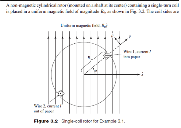
Example 3.1.A non-magnetic rotor having a single-turn coil is placed in a uniform magnetic field of magnitude 0.8 t, as shown in Fig.3.5. The coil sides are within a radius of 0.125 m, and the coil carries a current of 12 A, as shown. Determine the θ- directed torque as a function of rotor position α. The rotor may be assumed to be 0.5 m long.
Solution: The force per unit length on a wire carrying a current of I amperes can be determined by multiplying Eq. (3.4) by the cross-sectional area of the wire. As the product of the current density and the cross-sectional area of the wire is simply the current I, the force per unit length acting on the wire is given as
F=I×B
Thus, for wire 1 carrying a current of I amperes into the paper, the θ-directed force is given as
F1θ=IBl sinα
And for wire 2 located 180° away from wire 1 and carrying a current of I amperes out of paper is given as
F2θ=IBl sinα
where l is the length of the rotor in meters. The torque acting on the rotor is given by the sum of the force –moment-arm products for each wire i.e.
T=2 IBRlsin α =2×12×0.8×0.125×0.5 sin α =1.2 sin α N.M Ans.
3.3 ENERGY BALANCE
Since, for all practical purposes, the mass of the materials used in the construction of an electrical machine remains constant under the conditions of operation, the principle of conservation of energy can be applied in the analysis of the energy conversion. The input energy must, therefore, be equal to the summation of the useful output energy, the energy converted into heat, and the change in the energy stored in the magnetic field. Thus energy balance equation may be written as
(Energy input from electric sources )=(Mechanical energy output )+(Increase in energy stored in coupling field )+(Energy converted into heat ) Equation 1 (3.7)
Equation (3.7) is applicable to all conversion devices; it is written so that the electrical and mechanical energy terms have positive values for motor action. The equation equally well to the generator action; these terms then simply have negative values. For generator action
(Total mechanical energy input )=(Electrical energy output )+(Increase in energy stored in the magnetic field )+(Energy converted into heat )
Irreversible conversion of energy to heat arises due to three reasons; part of electrical energy is converted directly to heat in the resistance of the current paths, part of the mechanical energy developed within the device is absorbed in the friction and windage and converted into heat, and part of the energy absorbed by the coupling field is converted into heat in magnetic core loss (for magnetic coupling) or dielectric loss (for electric coupling). If the energy losses in the electrical system, the mechanical system, and the coupling field are grouped with the corresponding terms in Eq. (3.7), the energy balance equation may be rewritten as
(Electrical energy input less resistance or ohmic losses )=(Mechanical energy output plus friction and windage losses )+(Increase in energy stored in coupling field plus associated losses ) Equation 2 (3.8)
The left-hand side of Eq. (3.8) can be expressed in terms of the currents and voltages in the electric circuits of the coupling device. Consider, for example, the energy-conversion device shown schematically in